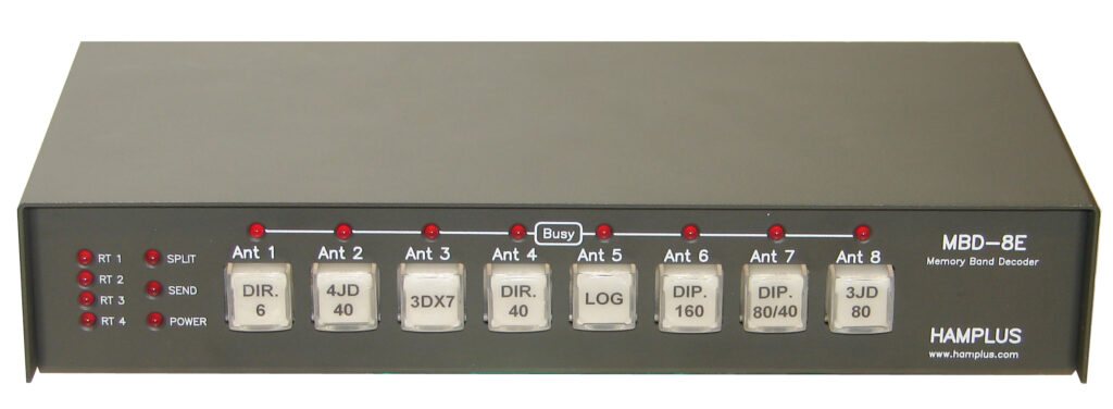
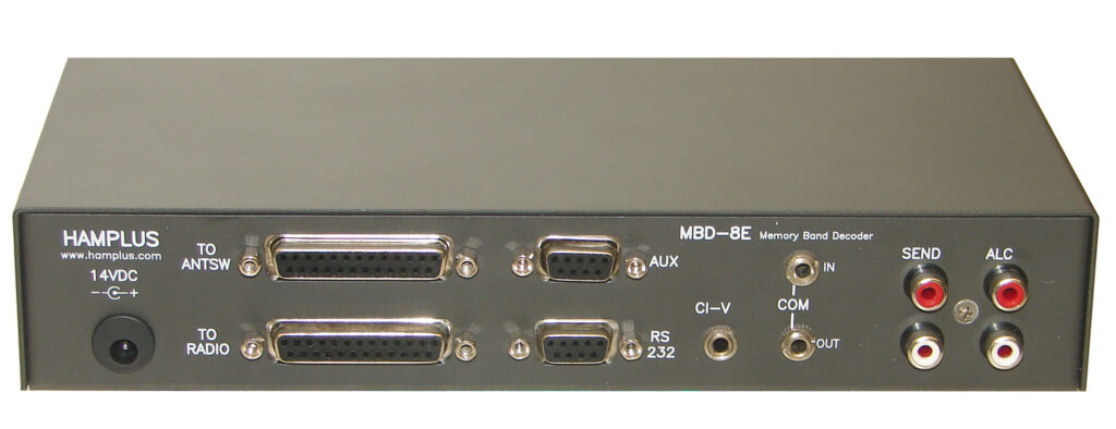
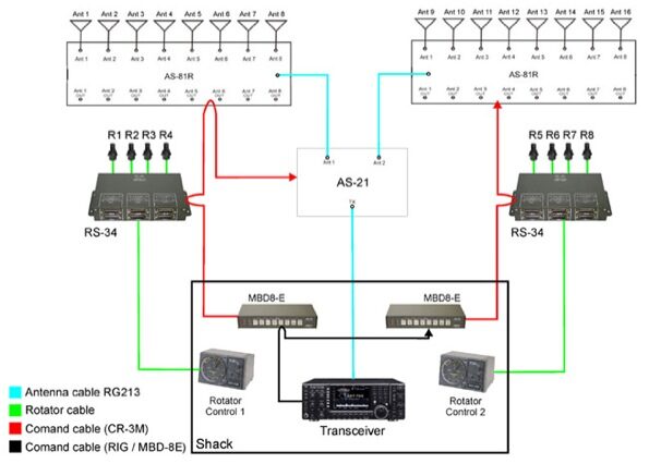
The MBD-8E is a remote control unit used to control antennas switchers. They have memory and band decoder. Each MBD-8E is able to control up to eight antennas through keys of momentary contact, illuminated by LED. By using two or more MBD-8E it’s possible to expand to 16 antennas or more. The illuminated keys indicates the antenna in use (Ant1 to Ant8). Each key also allows graphical identification (type of antenna, band, etc.).
To share eight antennas with a radio, the operator must use a antenna switch with its respective remote control MBD-8E, one for each radio. In this in case there are a line of red Led?s (Busy) to indicate witch antennas in use on the other radios. The system has a protection and the MBD-8E does not allow the same antenna is connected in more than one Radio at the same time.
Antenna Split:
With the MBD-8E it is possible to operate with one antenna for the transmission and another one for reception. The commutation of the antennas is automatically made when the MBD-8E receved the “Send” information from the transceiver.
Memory:
The memorization is automatic, just press a key of the desired antenna. Any one of the eight antennas can be used in any or all the bands. Whenever the radio will power ON or change the band, the last antenna chosen for that band will be set automatically.
Band Decoder:
The MBD-8E received from transceiver the power supply (13.8VDC), the “Send” line and the information about the band in use. The controller MBD-8E recognized the follow information about the band in use:
1- D.C. level (Icom)
2- CI-V (Icom)
3- BCD (Yaesu)
4- RS-232 (Kenwood, Yaesu, Icom)
Frequency Segmentation of antennas:
The MBD-8E allows frequency segmented antennas of short band. In such a way, the antennas that have a box for commutation of segment, can be commanded automatically by the MBD-8E. The commutation frequencies are selected and programmed by the user in very easy way and are recorded in not volatile memory.
Command output for the RS-34:
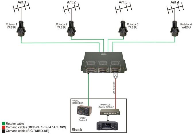
The MBD-8E has the command output to the rotator switch RS-34. On the front pannel there are four LED?s to indicate the rotor in use at the moment. The programming to associate the rotator to each antenna is one easy job made by the user in a couple of minutes. This configuration is saved in a not volatile memory.


