Introduction:
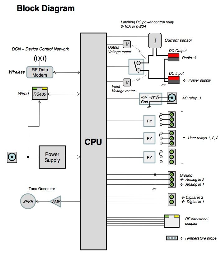
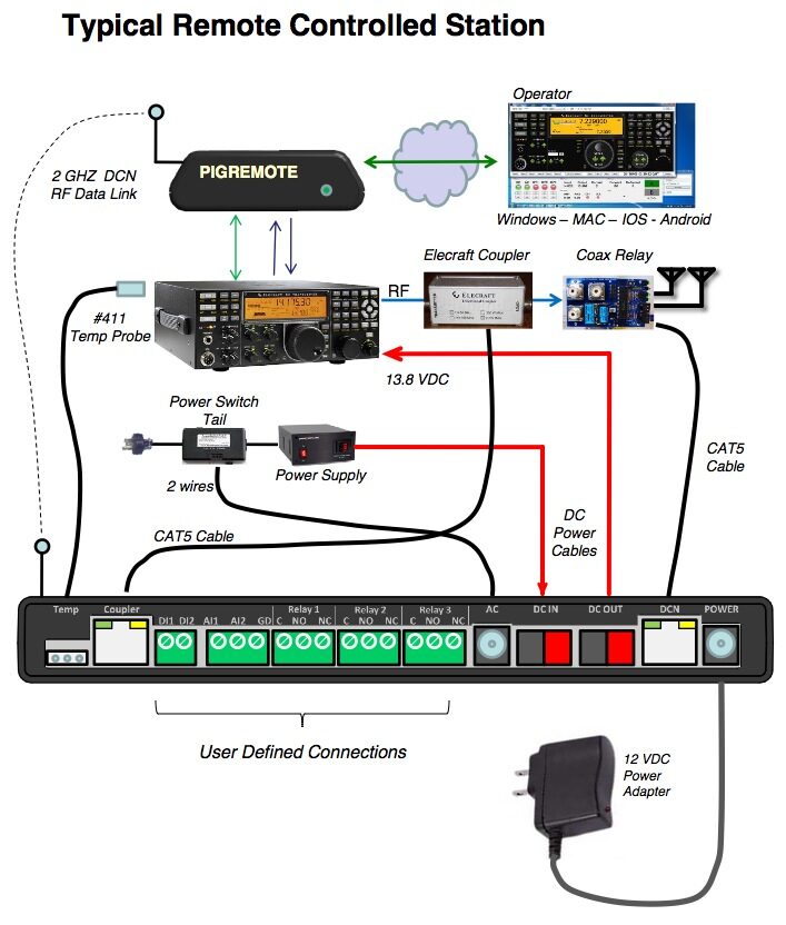
The Station Controller monitors and controls the environment in a remotely controlled ham station, repeater site or commercial radio installation. The Station Controller can monitor.
– DC voltage input
– Switched DC voltage out
– DC current
– Temperature
– RF power forward and reflected using an Elecraft directional coupler
– 2 user definable opto-isolated digital inputs
– 2 user definable 0-30 VDC analog voltage input
The Station Controller can control:
– Primary station DC power (10A, 20A or 30A latching relay options)
– AC power (up to 15A) with optional external AC power switch tail
– 3 user definable SPDT 2A small signal relays
Additional features:
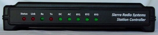
– 9 front panel LEDs to indicate system status
– Audio tone generator and built-in speaker for system status and alerts
– 10 pin HamStack LCD jack for optional LCD panel
– Firmware supports complex tone and CW generation
Firmware features:
The Station Controller supports the SRS DCN rev 1 specification. Control commands include setting relays, generating alert tones and CW, getting status of relays, digital inputs, analog inputs, RF power and temperature.
Master Control Software:
The Station Controller is compatible with the Pignology PigRemote station control system. The Station Controller communicates wirelessly with the Pignology system using the SRS DCN operating wirelessly on 2.4 Ghz .
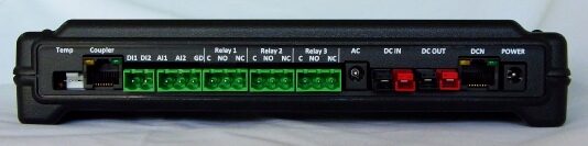
Chassis Rear View
From left to right: temperature probe jack, RF coupler jack, 2x digital inputs, 2x analog voltage inputs, external AC relay control port, 13.8 VDC power in & out, DCN network jack, 12v (7-16VDC) system power input. The green connectors are plug-in terminal block. The picture shows the sockets without the screw terminal block plugged in. These connectors provide the functionality of screw terminals and the convenience of a plug-in connector.
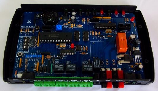
Internal View
Along the top you can see the socket for an Xbee RF data module, speaker, LEDs, slave CPU and LCD jack.
In the middle from left to right: 8 bit DIP switch for setting device network address and mode, main CPU, logic, DC power relay, current sensor and power supply.
Along the bottom you see the opto-isolators, small signal relays and connectors.
In this view you see the standard orange 10A DC power relay. To the left of the orange relay is a footprint for a larger 30 relay. When installed, the PCB traces are rated to handle 20 amps. With additional wire soldered in place, the relay can handle 30 amps.
Price: $249.95 USD