This interface is galvanic isolation of the transceiver from PC computer. Audio input and output paths are separated by transformers; optocouplers serve to isolate the digital paths, PTT and CW KEY.
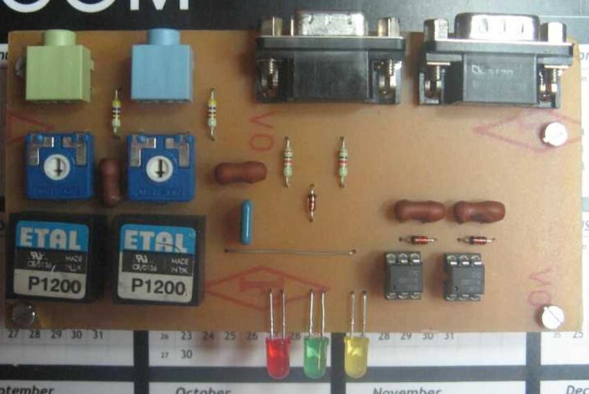
It was built for Icom IC-718 but can be used for any other radio. Interface support PTT keying over RS232 RTS (pin 7) and CW keying over RS232 DTR (pin4) line. LE diode LED2 glow green when radio is in RX state. LED3 glow red when PC software switch radio to TX state. If you use some of contest or logging software for automatic CW keying, LED 4 will glow in rhythm of Morse letters.
Connection from PC to interface goes to 9 pin subD female connector. It takes 3 pins:
- Pin 7 – RTS (RX/TX keying)
- Pin 4 – DRT (CW keying)
- Pin 5 – PC GND
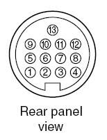
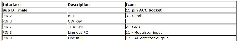
Connection from interface to TRX goes via 9 pin subD male connector. Same connector is used for audio channels from interface to TRX. This is connection cable for ICOM IC-718.
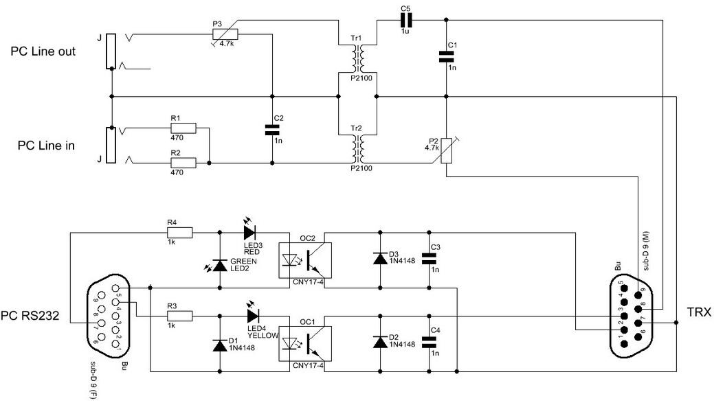
Download schematics as:
PCB layout
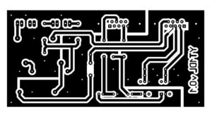
Download PCB layout as:
Download parts placement as:
Source: YT1DL