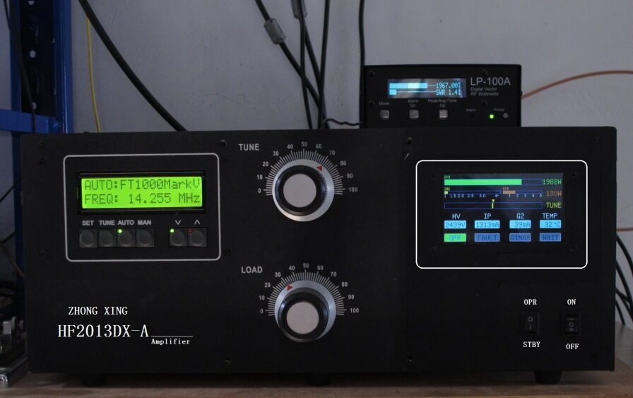
New QRO Chinese Zhong Xing automatic HF Linear Amplifier “HF2013DX-A”.
Important safety instructions:
–The amplifier contains high voltage circuits. Never turn the amplifier on without the upper lid in place.
–The amplifier is neither to be used in a wet or humid environment nor to be exposed to rainfall.
–The amplifier must be installed in such a way that free flow of hot air from the tube is allowed. The amplifier must not be installed in a constrained surrounding (i.e. tight shelves etc.)
–During long operation the upper lid and the vent grid of the amplifier can reach high temperatures that can cause burn injuries. Do not touch these parts of the amplifier during operation.
–The amplifier must be grounded during operation.
–During operation the amplifier must be installed in such a way that the rear power supplies are accessible.
–The amplifier can be operated only if both supply cables are connected. the amplifier reaches optimal parameters when it is connected to 2 phases.
–Do not turn the amplifier on without having connected the antenna. A hazardous HF voltage may build up on the antenna connector after turning the amplifier on with no antenna connected.
–Before opening the upper lid of the amplifier make sure that both power supplies have been disconnected for at least 5 minutes allowing the electrolytic capacitors to discharge fully. Never turn the amplifier on without the upper lid in place.
–Make sure that all screws holding the case together are properly in place and tied before carrying the amplifier by the handles.
–The amplifier is an A category product. In a household it can influence other electric appliances. In such cases the user is to take proper actions to mitigate this disturbance.
General description of the amplifier:
The linear amplifier the amplifier is designed for all short wave amateur bands from 1.8 till 29
MHz (including WARC иC bands) and all modes. It is equipped with a ceramic tetrode FU728F=(4CX1500). The amplifieris automatically tuned to operating frequency of your TRX.
Since 2010 with advanced technologies and selected materials, we began to manufacture Zhong Xing Power Amplifiers for global radio amateurs. Now we provide two models: manual HF2013DX and automatic HF2013DX-A. We received favorable comments from our customers after their two-year trials.
Specification of the amplifier:
Frequency coverage: amateur bands 1.8 иC 29.7 MHz including WARC
Power output: 2000 W in SSB and CW 1800 W in RTTY, AM and FM
Drive Power: usually 60 to 80 W for full Output Power
Input impedance: 50 Ohm VSWR < 1.5 : 1
Output amplification: 17 dB
Output impedance: 50 Ohm unbalanced
Maximum output SWR: 2:1
SWR protection: automatic switching to STBY, when reflected power is 350W or higher
Intermodulation distortion: 32 dB below nominal output
Suppression of harmonics: < -50 dBc
Tuning manual or AUTO
Response speed of AUTO less than 0,5s within same BAND Less than 3s if out of BAND
Supported TRXs-CAT ICOM, ELECRAFT, KENWOOD, TEN-TEC, YEASU and Icom transceive protocol using by microHAM
devices CI-V OUPUT
Tube: FU728 Ceramic tetrode
Cooler: EBM Centrifugal blower + axial blower
Power supply: 2 x 230 V – 50 Hz one or two phases
Transformers: 2 pcs of toroidal transformer 2,0 kVA
Protection circuits: – SWR too high
– anode current too high
– screen current too high
– grid current too high
– Mistuning of power amplifier
– Hot switching protection
– Soft start for protecting your fuses
– switchиCon blocking at opened amplifier
Bar graph indications: – Power output bar graph 50 LED
– reflected power bar graph 20 LED
– screen current ( Ig2 иC bar graph 10 LED )
– anode voltage, anode current, tuning bar graph 30 LED
LED indicators : grid current ( Igl 2 LED )
WAIT – preheating of tube (180 sec )
STBY – standby
OPR – operating condition
FAULT – failure, switching off for abt. 2 sec
OSD Indication LCD display 2×16 Characters
Parameters: 485 x 200 x 455mm (width x height x depth)
Weight: 35 kg
General Description of the amplifier:
HF PART
In this amplifier a tetrode FU728F is used in a grounded-cathode circuit (input into control grid). This amplifier achieves excellent linearity by the voltage stabilization of the control grid bias and the screen voltage. The power input is given to the control grid, using a broadband input circuit with an input impedance of 50 Ohms. This adaptable input circuitry ensures a good input SWR better than 1.5:1 on all short-wave bands.
The output of the amplifier is a Pi-L circuit. The ceramic capacitor for TUNE and LOAD are divided. This enables the amplifier to be tuned exactly and makes it possible to easily return to the previously set positions after band change.
Tetrode FU728 PWR meter EBM Blower switch -on board
Output Pi-L Circuit Tuning capacitor Power supply board
POWER SUPPLY
Power supply of the amplifier is effected by two 2,0 kVA toroidal transformers. A soft start is realized with the help of relays and resistors.
The high anode voltage consists of 8 times 420V and 2A. Each of them has its own rectifier and filter. In the high voltage circuit safety resistors are employed to protect the amplifier against overload. The source for screen grid is stabilized by a parallel stabilization with BU508 transistors and delivers a voltage of 360V at 100mA.
The -120V for the control grid is stabilized by means of zener diodes.
SAFETY DEVICES
Control and monitoring circuits ensure control and safety of the circuits of the device during malfunction of the PA. They are placed on the Control board, which is located on the subpanel.
Putting the power amplifier into operation Coaxial cable
The output of the transceiver is to be connected with the input of the amplifier via RG58 or similar cable. For the connection between the power amplifier and the antenna via RG213 or similar coaxial cable suited for this high power is to be used. For INPUT and OUTPUT PL-259-sockets with Teflon isolation are used.
Mains plug1 Mains plug2 Fuses OUTPUT
REMOTE I / O Interface INPUT
MAIN SUPPLY
The amplifier is connected to the mains with 2 cables with a EURO end. Each cable is to be switched to another phase of your main supply system! Both of them have to be able to deliver a power of 2.0 kVA !
If you use only one phase, you have to connect both cables to this one phase! Your main supply has to be able to deliver 4 kVA on this one phase! In this case the power amplifier canбпt deliver full output!
ATTENTION
In each case the power amplifier has to be connected to your main supply system with 2 cables! Normally the amplifier is used with 2 phases. If there is only one phase – connect both cables to the single one!
Grounding:
The amplifier has to be grounded properly! Connect the screw on the rear panel of the amplifier to your local grounding system with a copper-cable; use a cross-section of 4 mm at least.
Connect your transceiver to the same grounding system of your shack carefully!
If you use a power amplifier with higher output you have to be aware that your grounding system works properly. All parts have to be grounded to the same system. Use short cables and make sure that there are good contacts! Otherwise you run the risk of damaging your equipment, having problems with TVI/BCI or your signal may be distorted.
REMOTE
Control of the amplifier is possible remotely by using REMOTE BOX (optional). Connection is done by REMOTE socket, maximum cable length of 10 meters.
I / O box Control of Amplifier and communication with TRX as well as antennas / BPF switching can be done via I / O Interface
KEY IN – Input signal PTT (switching voltage / current 5V / 2mA)
KEY OUT – Output signal PTT (maximum switching of 30V / 50mA)
Control cable
Control cable maintains TX / RX switching of the PA (TX GND). The cable is shielded. On the side of the power amplifier a CINCH-socket is used. On the side of your transceiver you have to use a socket suitable for this transceiver. During transmitting the middle pin is connected to the ground.
The relays of the amplifier have to be switched earlier than HF is applied (cold switching).
Modern transceivers have a time delay between PTT switching and power output.
If you are using and older transceiver or transmitters without time delay we recommend to connect the PA in such a way that the transmit/ receive switch is connected with the KEY IN socket of the amplifier. The KEY OUT socket is to be connected with the PTT socket at the transceiver.
The amplifier is equipped with two safety devices, which ensure that the Output relay is not switched under power mistakenly (hot switching).
CI-V – Mono 3.5mm Jack for connection of ICOM TRXs. For successful operation selection of ICOM radio and correct baud rate is important (9600 default)
TCVR – DB-9 -serial port RS232 for YAESU and ELECRAFT TRXs. Correct baud rate and TRX type is a must for successful operation. If both CI-V and TCVR cables are used then CI-V wins over RS232. Otherwise selection of interface is done via TRX type.
PC – DB9 RS232 port is used for communication of your TRX with PC. Please use setting you would normally use as if using direct TRX иC PC connection.
ALC – RCA-Phono иC Automatic Level Control is used when tuning the PA to block drive level. WARNING!!! We recommend to use this feature mainly while operating RTTY, FM and other 100% duty modes.
CONTROL – DB15 connector for use of single cable between PA and TRX.
PIN OUT:
1. ALC Out
2. NC
3. INHIBIT Control voltage
4. TX INHIBIT for Yaesu and Elecraft иC this supersedes ALC output
5. NC
6. KEY OUT
7. NC
8. KEY IN
9. иC
15. GND
ANT & BPF SW – r DB-25 is used for switching of external HP BPF or external Antenna Switch. Maximum switching of 30V / 0.5A is possible.
PIN OUT:
1. antenna port 1
2. antenna port 2
3. antenna port 3
4. antenna port 4
5. antenna port 5
6. antenna port 6
7. antenna port 7
8. antenna port 8
9. antenna port 9
10. antenna port 10
11. COMMON port of ANT SW
12. NC
13. GND
14. BPF 160m
15. BPF 80m
16. BPF 40m
17. BPF 30m
18. BPF 20m
19. BPF 17m
20. BPF 15m
21. BPF 12m
22. BPF 10m
23. COMMON BPF port
24. NC
25. GND
Cooling:
The centrifugal blowers provide the necessary cooling of the amplifier, even during long contests. The main blower is activated by switching the PA on and it is turned off when after-cooling is finished (approx. 1-5 min after switching off the PA depending on the temperature of the tube). The supplemental fan is turned on depending on the temperature of the air exiting from the amplifier. It is switched on at 70буC and switched off at 60буC.
Operating elements:
TUNE – Anode capacitor for tuning, tuning of higher frequencies to “0”,Lower frequencies to 100.
LOAD – Output capacitor tunes antenna load resistance to amplifier.
Capacity is low at 100 and high at “0” on the scale.
OFF – You switch off the amplifier by pressing this button.
ON – You switch on the amplifier by pressing this button.
Heating of tube is on and after 3min of delay the amplifier will be ready for operation.
OPR/STBY – OPERATE puts unit ready for operation.
At STBY, if WAIT-LED is on or the amplifier is off your transceiver is in bypass-mode directly connected to antenna. Maximum 400 Watts!
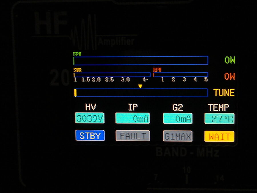
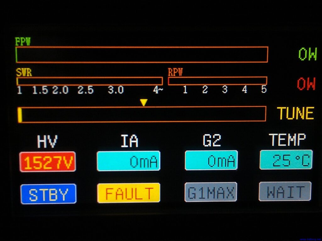
RF OUTPUT – Bar graph иC shows output power.
REFLECTED POWER – Bar graph иC shows reflected power of the antenna. 350W
maximum or amplifier switches to STANDBY-mode Ig2 bar graph – measures the currency of the second grid in the range from -20mA to +80mA
HV/IP/TUNE bar graph – measure the anode voltage, anode currency or tuning of the amplifier
INHIBIT – indicates interruption of operation during the tuning process of the PA. If indicated by RED LED then PA is in STBY mode. If retuning within same BAND then PA will retune according to QRG of TRX. When changing the BAND иC INHIBIT will stay lid till KEY IN is triggered for even short period and tuning process will start. After that PA is automatically ready for operation.
ANT, ANT1, ANT2 иCPA is capable of automatic antenna switching (ie. 80m CW and 80m SSB can be split between two antennas. PA will automatically select desired antennas by selecting last used antenna on given frequency.
Indication of fault conditions the amplifier has the following indication LED on the front panel:
GRID MIN – indication of first gird current
GRID MAX – max. First grid current exceeded
HV – measuring of anode voltage by bar graph
IP – measuring of anode currency by bar graph
FAULT иC fault
OPR – amplifier in operation mode
STBY – amplifier in standby mode
WAIT – heating of tube after switching on the amplifier
Should a fault condition appear during the tuning or operation of the amplifier the safety
circuits of the amplifier will react. The amplifier will be turned to STBY mode. After approx. 1 sec the control circuits will switch the amplifier back to OPR. If the fault will repeat 3 times
after each other the control circuits will turn the amplifier to STBY. Brining the amplifier to
OPR is enabled by using the OPR/STBY switch.
After the reaction of safety circuits the FAULT LED will be lit up for approx. 5 sec
depending on the nature of the fault.
Flashing LED signalizes:
IP – anode currency exceeded
HV – low anode voltage
FAULT – reflected output exceeded
GRID MAX – first grid currency exceeded
– screen grid currency exceeded
GRID MAX + HV – maximum load power exceeded
GRID MAX + IP – zero output power during tuning
HV + IP – tuning fault, incorrect tuning of the Pi-L output circuit
In case your amplifier is not working correctly, please contact the manufacturer or your distributor.
Price: TBD
For further information, please contact by email: bg7jaa@live.com


