
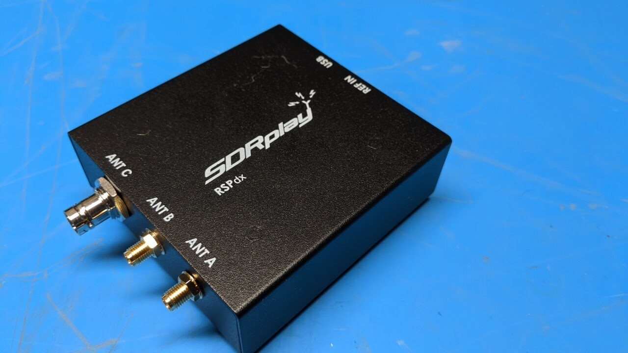
RSPdx Multi antenna port 14 bit SDR
The SDRplay RSPdx is a complete redesign of the popular RSP 2 and RSP 2 pro multi antenna receiver. It’s a wideband full featured 14 bit SDR which covers the entire RF spectrum from 1 kHz to 2 GHz. Combined with the power of readily available SDR receiver software (including SDRuno supplied by SDRplay) you can monitor up to 10 MHz spectrum at a time. The RSPdx provides three software selectable antenna inputs, and an external clock input. All it needs is a computer and an antenna to provide excellent communications receiver functionality. A documented API allows developers to create new demodulators or applications around the platform.
KEY BENEFITS & FEATURES:
- Covers all frequencies from 1kHz through VLF, LF, MW, HF, VHF, UHF and L band to 2GHz, with no gaps
- Receive, monitor and record up to 10MHz of spectrum at a time
- Performance below 2MHz substantially enhanced improved dynamic range and selectivity
- Software selectable choice of 3 antenna ports
- Enhanced ability to cope with extremely strong signals
- External clock input for synchronisation purposes, or connection to GPS reference clock for extra frequency accuracy
- Excellent dynamic range for challenging reception conditions
- Free use of windows based SDRuno software which provides an ever increasing feature set
- Strong and growing software support network
- Calibrated S meter/ RF power and SNR measurement with SDRuno (including datalogging to .CSV file
- Documented API provided to allow demodulator or application development on multiple platforms
APPLICATIONS:
Amateur
- Shortwave Radio Listening
- Broadcast
- DXing (AM/FM/TV
- Panadaptor
- Aircraft (ADSB and ATC)
- Slow Scan TV
- Multi-Amateur Band Monitoring
- WSPR & Digital Modes
- Weather Fax (HF and satellite)
- Satellite Monitoring
- Geostationary Environmental Satellites
- Trunked Radio
- Utility and Emergency Service Monitoring
- Fast and Effective Antenna Comparison
Industrial
- Spectrum Analyser
- Surveillance
- Wireless Microphone Monitoring
- RF Surveying
- IoT Receiver Chain
- Signal Logging
- RFI/EMC Detection
- Broadcast Integrity Monitoring
- Spectrum Monitoring
- Power Measurement
Educational/Scientific
- Teaching
- Receiver Design
- Radio Astronomy
- Passive Radar
- Ionosonde
- Spectrum Analyser
- Receiver for IoT Sensor Projects
- Antenna Research
SPECIFICATIONS:
General
- Weight 315g
- Size: 113mm x 94mm x 35mm
- Low current consumption:
- 190mA @ >60MHz excl Bias T)
- 120mA @ <60MHz excl Bias T)
Connectivity
- USB 2.0 (high speed) type B socket
Frequency Range
- Continuous coverage 1kHz 2GHz
Antenna A Port Characteristics
- 1kHz 2GHz operation
- 50 Ohm input impedance
- SMA female connector
Antenna B Port Characteristics
- 1kHz 2GHz operation
- 50 Ohm input impedance
- SMA female connector
- Selectable 4.7V DC out (see Bias T)
Antenna C Port Characteristics
- 1kHz 200MHz operation
- 50 Ohm input impedance
- BNC female connector
Reference Clock Input
- MCX female connector
Bias T (Antenna B Port only)
- Software selectable 4.7V @ 100mA
IF Modes
- Zero IF, All IF bandwidths
- Low IF, IF bandwidths ≤ 1.536MHz
IF Bandwidths (3dB)
- 200kHz
- 300kHz
- 600kHz
- 1.536MHz
- 5.0MHz
- 6.0MHz
- 7.0MHz
- 8.0MHz
ADC Characteristics
- Sample frequency 2 10.66MSPS
- 14 bit native ADC (2 6.048MSPS)
- 12 bit (6.048 8.064 MSPS)
- 10 bit (8.064 9.216MSPS)
- 8 bit (> 9.216 MSPS )
Maximum Recommended Input Power
- 0dBm continuous
- 10dBm for short periods
Reference
- High temp stability 0.5PPM TCXO
- In field trimmable to 0.01ppm.
External Reference Clock
- When an external 24MHz clock is applied, auto detect will switch to the external reference. Ideally the external clock source should be connected to the RSPdx before power up
Typical Noise Figures
- 20dB @ 2MHz
- 17dB @ 12MHz
- 15dB @ 25MHz
- 15dB @ 40MHz
- 2.6dB @ 100MHz
- 2.1dB @ 200MHz
- 6.0dB @ 340MHz
- 3.1dB @ 660MHz
- 4.4dB @ 1500MHz
- 5.0dB @ 1800MHz
Notch Filters
FM Notch Filter:
- >30dB 77 – 115MHz
- >50dB 85 – 107MHz
- >4dB 144 – 148MHz
MW Notch Filter:
- >15dB 400 – 1650kHz
- >30dB 500 – 1530kHz
- >40dB 540 – 1490kHz
DAB Notch Filter:
- >20dB 155 – 235MHz
- >30dB 160 – 230MHz
Note: The notch filters above are
software selectable and remove
specific broadcast bands.
Front End Filtering
Low Pass
- 500kHz
- 2MHz
Band Pass
- 2 – 12MHz
- 12 – 30MHz
- 30 – 60MHz
- 60 – 120MHz
- 120 – 250MHz
- 250 – 300MHz
- 300 – 380MHz
- 380 – 420MHz
- 420 – 1000MHz
High Pass
- 1000MHz