R&S FK2910: 2 kW R&S FK2920: 4 kW
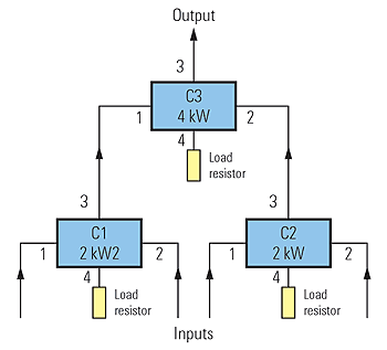
The power combiner section consists of three individual couplers, arranged at two levels so as to maximize the power management possibilities.

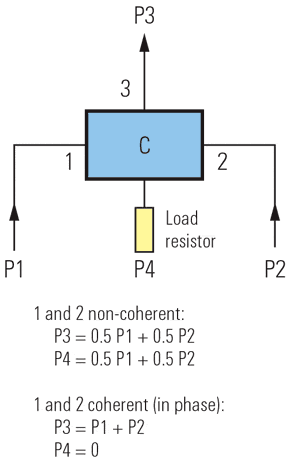
The individual couplers are zero-degree couplers. This ensures perfect power combination if the two inputs are in phase (coherent combining). The coupling device is designed as a four-port system, which provides two inputs, one RF signal output, and one output to the balance load. The function is explained by means of the following simple example:

Two exciter signals P1 and P2 are applied to the inputs of the coupler, which behaves differently according to whether the two signals are
A: identical – coherent and in phase
B: not identical, not coherent.
Coherent means that the signals originate from the same source (modulator) and are thus in phase.
Case A:
At the output of the coupler, the sum of the powers of the two signals (P3 = P1 + P2) appears. The residual loss is typically less than 0.4 dB.
Case B:
At the output of the coupler, the sum of the half powers of the two signals (P3 = 0.5 ? P1 + 0.5 ? P2) appears. The loss of one signal is typically between 3.2 dB and 3.4 dB. The loss of 3 dB, which is caused by the non-coherent combination, is dissipated in a load resistor connected to the fourth port of the coupler.
This typical behavior of a coupler allows the coupler loss to be controlled by appropriate and intelligent selection of the input signals, which in practice is the task of the power management unit. The unit is controlled by the operator from the comms workstation in the operator console.
The second noteworthy property of a zero-degree power coupler is its isolation. This means that a signal P1 fed into one input (e.g. input 1) appears at output 3, not at input 2. Thus the two power sources are decoupled, and intermodulation between the signals is virtually eliminated.
The nominal insertion loss is between 0.2 dB and 0.4 dB. The coupling loss is 0 dB case A and 3 dB case B.
The isolation of the coupler typ. –25 dB for adjacent lines, higher for non-adjacent lines – determines the backdoor intermodulation in the power amplifiers. The primary source of backdoor intermodulation is therefore between two adjacent power amplifiers that are combined by a coupler. The amplifier-to-amplifier paths in the combiner add a multiple of 3 dB to the isolation. Each coupler can accept a maximum of 1122 W (R&S® FK2910) or 2 kW (R&S® FK2920) input power per input port.
Since the power combining unit consists only of passive and solid-state devices, there are no limitations on frequencyagile EPM (ECCM) operating modes and frequency separation between the various HF transmitting channels.
In addition, these passive devices feature an outstanding MTBF figure up to 18000 h (depending on the operational configuration, power levels used, coherent or non-coherent, etc) and thus excellent availability.

