SDU-X: SOFTWARE DEFINED DATA TRANSMISSION WITH ULTRASONIC TRANSDUCERS.
 Damian needed to get telemetry from his off-grid solar system 150 feet away, but didn’t want to spin up another unreliable WiFi device. Instead he came up with a clever solution that involves using ultrasonic transducers as the physical layer of a software defined communications system instead of RF transmitters and receivers.
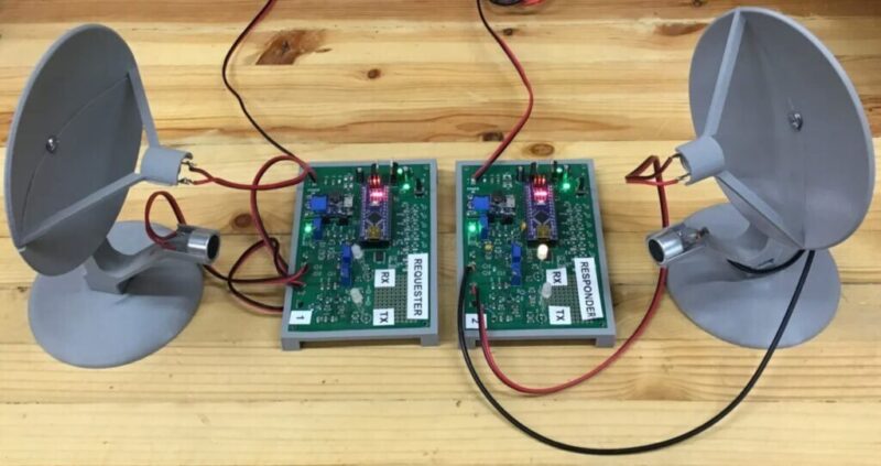
Having worked on RF communications systems before, Damian knew that the same concepts apply no matter what the physical layer of communication is. His system called SDU-X uses two ultrasonic transducers mounted on 3D printed parabolic dish’s to increase the directional gain, and an Arduino Nano with amplifiers and a Digital to Analog (DAC) converter for the ultrasonic transmission.
His post explains the hardware and protocol implementation, as well as explaining the Arduino code that he’s released for free. The code and 3D printer models can be found on Thingiverse.
The SDU-X system
Figure 2 shows the general design of a system I am calling the Software Designed Ultrasonic Transceiver or the SDU-X. The figure shows a minimum number of parts: a couple of ultrasonic transducers, a receiver amplifier/bandpass filter, an Arduino Nano, a DAC, and a transmit amplifier. Not shown is a handful of things like power supplies and some LEDs.
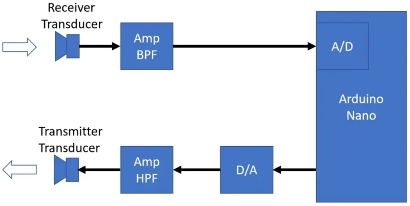
Figure 2 The SDU-X design with a minimum number of parts excluding power supplies and LEDs.
To assist in signal reception, there is a 3D printable parabolic dish for the receiver transducer. This dish mounts on a 3D printable tower that holds the transmitter transducer and has a set of sighting holes for aiming the dish. The dish gives about a 9 dB improvement in reception.
Current code allows for selection of different modulation types. Some are fully implemented for sending and receiving. Some are only implemented as transmitters and the receiver for that modulation type is something the user can experiment with creating. It is intended as something like a student exercise.
An SDU-X system, consists of two assemblies: one is called the Requester and the other the Responder. The hardware (PCBA) is the same for both, but they have different compiles of the firmware. When running, the Requester will send out a transmission asking for data from the Responder or for an action to be executed by the Responder. In the current firmware, the requested data can be something like the Responders SNR measurements, or a value from onboard analog input or digital I/O status. This data is transmitted back to the Requester who can then print it out on a serial port (available in the Arduino IDE). Requested actions can, for example, include having the Responder blink its LEDs or set some digital I/O high or low.
Schematic
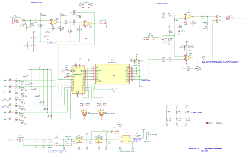
Schematic of the SDU-X system with the receiver transducer (upper left) and transmitter transducer (upper right).
On the upper left side, we see the receiver transducer connected to an op-amp (U1A) acting as a band-pass filter with an adjustable gain of up to 100 (40 dB). Typically, this gain is just set to the maximum, unless the units are a few feet apart. The -3 dB roll-off frequencies are at about 7 kHz and 90 kHz. The transducer itself is also a good filter centered at 40 kHz. From my testing the 40 kHz acoustic band seems to be pretty quiet, so filtering of the input is not very critical.
Following the first stage is an op-amp (U1B) configured as a Sallen-Key band-pass filter with a gain around 10 (20 dB). When combined with the first stage, the receiver amplifier gives a total gain of 1000 (60 dB). The -3 dB roll-off frequencies of the combined two stages are at 38 kHz and 42 kHz, cleaning up the signal even further. The 0 to +5 V output of this amplifier is then run to an analog input pin of the Arduino Nano which is internally connected to the Nano’s 10-bit ADC.
Moving to the upper right of the schematic, we can see a pair of op-amps. The upper one (IC U6A) is configured as a non-inverting amplifier with a high-pass response rolling off -3 dB at around 1.5 kHz. The lower op-amp (IC U6B) circuit is configured as an inverting amplifier with about the same high pass response. When the outputs of these circuits are tied to the transmitter transducer they act as a differential driver, allowing the transducer to see a signal of approximately +/-12 V. Low-pass output filtering relies on the filter characteristics of the transmit transducer, which works very well. The transducer response rolls off -3dB at roughly +/-1 kHz. Note that the two resistors (R37 And R38) on the output the op-amps are to aid in stability, if needed, in driving the highly capacitive transducer. The input to these two op-amps comes from an 8-bit DAC (IC U3) which is driven directly from the Nano. Note that the two dual op-amps are TL082’s, selected primarily for the slew rate.
That’s essentially the complete direct sampling systems hardware.
A few more parts round out the schematic. The power supply generates 3 voltages; +8 VDC to power the Nano, +5 VDC to power the receiver op-amps and LEDs, and +15 VDC to power the transmit circuits op-amps. There are a couple of red/green bi-color LEDs on the board also, along with a few green LEDs for power indicators. The output power is a 10 to 13 VDC at 100 mA minimum. A simple AC adapter works fine.
There are spare digital I/O and analog inputs and a small proto area for experimentation and new features. Also, on the PCB are several strategic test points to monitor analog in and out as well as for use in monitoring streams of internal data such as received samples, correlation shape, flagging sync times, etc. Some test points are appropriately spaced and sized to allow for use with an oscilloscope probe ground spring for convenient hands-free probing.
In the next installment, we will look at the firmware in the SDU- X. In the meantime, the PCB, schematic, 3D files for the parabolic towers, design notes, and firmware can be found at: https://www.thingiverse.com/thing:6268613
Damian Bonicatto is a consulting engineer with decades of experience in embedded hardware, firmware, and system design. He holds over 30 patents.